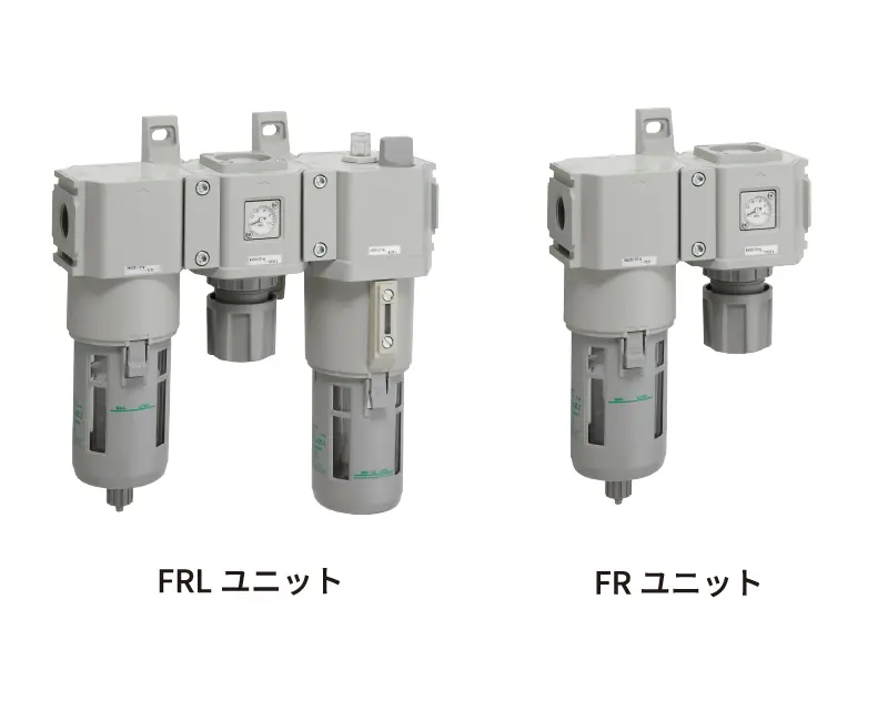
It consists of an air filter, regulator (pressure reducing valve), and lubricator to adjust the air supplied to the equipment (removal of foreign matter, etc., pressure adjustment, lubricant spraying).
It is called an F.R.L. unit (or 3-point set).
With the spread of oilless equipment in recent years, FR units (filter regulators), which consist of an air filter and regulator, are increasingly being used.
In addition, FMR. units (filter, mist filter, regulator), etc., combine oil removal filters to suit the degree of air cleanliness required on the equipment side.
The air filters remove moisture and foreign matter in the piping after the main line filter and air dryer to prevent problems before they occur.
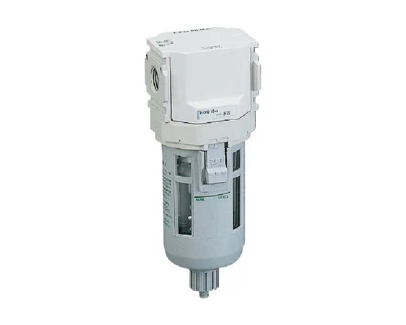
Structure and Filtration Principle of Air Filters
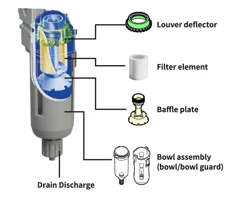
Compressed air entering from the inlet is swirled by (1) the louver deflector, and due to its cyclonic effect, large foreign matter, water droplets, and oil droplets are centrifugally separated and placed against the inner wall of the bowl assembly (4), where they accumulate on the lower part of the wall.
Fine particles that cannot be centrifugally separated are further filtered by the filter element (2) and sent to the outlet side.
(4) Periodically discharge the drainage accumulated in the bowl assembly from the (5) drain outlet.
CKD's Leading Products
The inside of the filter consists of a louver deflector, a filter element, a baffle plate, and so on.
Louver deflector
Dirty air is first swirled by the built-in louver deflector (cyclone effect) to centrifugally separate large particles, drainage, and oil mist (40 to 500μm).
Filter element
The typical solid removing element used in the FRL is around 5 to 10 μm. However, an oil removing filter element with a filtration rating of 0.3 μm is also used to remove oil, tar and carbon.
Baffle plate
Prevents drainage separated by the louver deflector from being lifted up.
Bowl assembly (bowl / bowl guard)
Generally, the bowl material is a clear, colorless resin (polycarbonate).
However, since this polycarbonate is susceptible to acid and alkaline atmospheres, a change in material (metal) should be considered in such environments.
In addition, the resin bowl comes with a set of bowl guards to prevent the scattering of debris in the event of bowl breakage.
Air Filter Drain Discharge
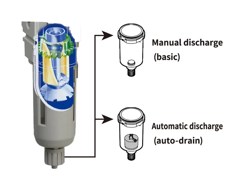
There are two drain discharge methods for the air filter.
Manual discharge (basic)
Visually check the drainage accumulated, and open the drain cock by hand to discharge.
Automatic discharge (auto-drain)
When a certain amount of drain is accumulated, the automatic discharge valve in the bowl is activated to discharge the drainage.
NO and NC types are available.
Differences between
NO and NC auto-drain types
NO (open when not pressurized)
Features
Drainage is discharged naturally when not pressurized (at night, etc.), so manual discharge is not required.
In the pressurized state, drainage is automatically discharged when it accumulates to a set level.
Cautions
Since air and drainage are temporarily discharged until the pressure above the minimum working pressure is filled, compressors with a small discharge flow rate (0.75 kW or less) may not be able to fill the pressure.
Use an NC type in this case.
NC (closed when not pressurized)
Features
This type is suitable for a compressor (0.75 kW or less) having a small discharge.
There is no temporary air purging during pressurization.
Once pressure is maintained, drainage is automatically discharged when it accumulates to a set level.
Cautions
Drainage is not discharged without pressurization (at night, etc.), so manual discharge is required in applications where large amounts of drainage are generated in this state.
Air filter flow characteristics
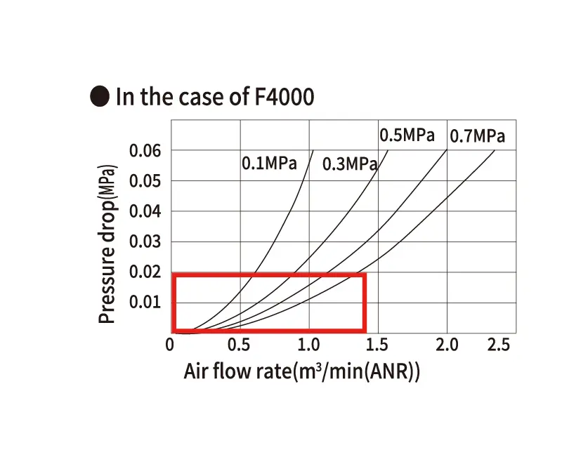
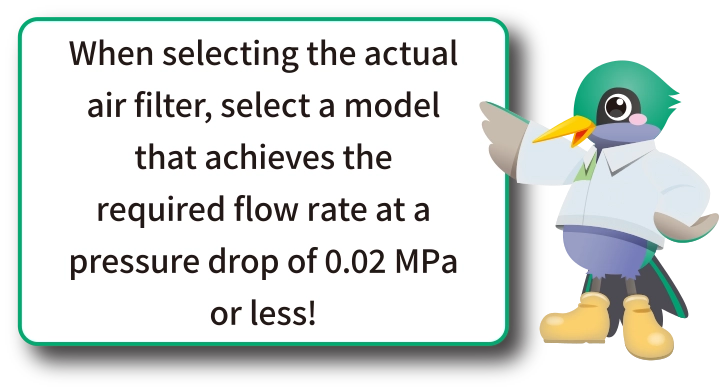
When compressed air flows through an air filter, a pressure drop (*) occurs during the filtration process.
The flow characteristic chart on the left shows the relationship between air pressure, pressure drop, and flow rate.
The larger the flow rate, the greater the pressure drop.
*Pressure drop: the energy loss per unit time and unit flow rate when a fluid passes through a mechanical equipment, etc.
