What is an Inline Filter? A Thorough On-Site Explanation of Its Mechanism, Types, and Selection
An inline filter is an essential small filter in equipment maintenance, installed midway in pipelines to remove foreign particles from fluids.
Choosing the wrong type or material may lead to pressure loss or reduced lifespan.
This article details everything—from basic principles and types to professionals' "fail-proof selection criteria" and maintenance practices—from an equipment maintenance perspective.
What Is a Filter?
In pneumatic systems, a "filter" refers to equipment that removes impurities such as drain (moisture), particles, and oil from compressed air generated by a compressor to supply clean air.
Compressed air from a compressor inherently contains atmospheric particles, moisture, and oil mist generated during compression. If these flow directly through pipelines, they can damage cylinder seals, cause solenoid valve malfunctions (minor stoppage), or, in the worst case, lead to foreign matter contamination in products.
To prevent such issues, the basic approach is to install appropriate filters in the compressor room or main pipelines to maintain air quality.
Generally, equipment referred to as "air filters" includes the following types, depending on the target contaminants:
| Types | Role and Removal Targets |
|---|---|
| General-Purpose Air Filter | The most basic filter that removes relatively large solid particles (debris) and drain (moisture). |
| Oil Removal Filter | Removes oil mist, tar, and carbon contained in compressed air. |
As such, even if thorough measures are taken upstream, new debris (rust or pipe fragments) can still form while passing through long piping.
Therefore, the "inline filter" explained here is used to reinforce the final line of defense right before (at the endpoint of) equipment. In the next chapter, let’s take a detailed look at the features of inline filters.
Basic Knowledge of Inline Filters
True to its "inline" name, this filter is installed mid-pipeline and serves a fundamentally different role from large filters at the source. First, we will explain its definition and the clear distinctions from easily confused similar products (strainers and inlet filters).
What is an Inline Filter?
An inline filter is a device directly installed in the pipeline to remove fine contaminants from fluids. It functions by being placed immediately before end-use equipment such as solenoid valves, cylinders, vacuum pads, as well as sensors and controllers.
In manufacturing plants, primary filtration is performed by large filters installed in compressor rooms, but new contaminants can still arise within the piping leading to end-use equipment. Examples include seal tape fragments, rust from aging, and metal shavings from pipe processing. The inline filter acts as the last line of defense against such "in-line generated contaminants," preventing equipment failure.
It is especially indispensable in processes where fluids are directly "delivered or applied" to workpieces. By passing fluids through inline filters in final-stage operations like air blow or vacuum suction—where fluids contact products—product scratches, quality defects, and contamination are preemptively prevented, directly safeguarding production quality.
Etymology of "Inline" and Installation Position Characteristics
Inline means "mid-pipeline." Unlike large mainline filters installed at the source (e.g., compressors), the key feature of inline filters is their placement immediately before end-use equipment for final capture.
While mainline filters handle bulk filtration for the entire system, inline filters protect individual devices (solenoid valves, cylinders, vacuum pads, analyzers, etc.).
Differences from Main Line Filters, Strainers, and Inlet Filters
Let’s clarify the distinctions from similar products.
| Product Name | Installation Location | Primary Application |
|---|---|---|
| Inline Filter | Mid-pipeline (immediately before end-use equipment) | Final removal of fine contaminants. Protects individual equipment such as solenoid valves and cylinders. |
| Main Line Filter | Immediately after the compressor (upstream) | Primary filtration for the entire system. Removes coarse contaminants. |
| Strainer | Upstream side of piping (mainly for liquid piping) | Removal of large contaminants. Captures visible-sized particles like sand and rust flakes with a mesh filter. |
| Inlet Filter | Equipment air intake (inlet) | Prevents external dust intrusion. Blocks foreign particles from entering the equipment. |
Why are inline filters necessary? The "invisible risks"
Even with high-performance main filters installed at the source, why do issues occur at the endpoints? The answer lies in the contaminants generated inside the piping after passing through the compressor.
Contaminants generated in pipelines (seal tape fragments, rust, metal shavings).
The main contaminants generated in pipelines include the following:
Cut ends of seal tape.:The sealing tape wrapped during joint connection gradually peels off due to pressure fluctuations and vibrations. Microscopic fiber fragments invisible to the naked eye get caught in the solenoid valve spool, causing operational failure.
Rust due to aging deterioration.:Rust formed on the inner surfaces of iron pipes or fittings detaches and is carried downstream by the fluid flow. Especially in older factory equipment, invisible fine rust particles constantly flow through the system.
Machining chips.:Metal fragments generated during pipe cutting or threading may remain inside the piping. During initial operation, these can flush out all at once, sometimes instantly damaging new equipment—a not uncommon occurrence.
Since these contaminants originate downstream of the source filter, final removal at the endpoint is essential.
The value as "insurance" to protect expensive equipment.
In manufacturing sites, the risk of minor foreign matter causing sudden equipment stoppages is an everyday concern. Inline filters function as "insurance to protect costly equipment." While the filter unit itself costs only a few thousand to tens of thousands of yen, the cost-benefit becomes clear when considering downtime losses per hour. Particularly in 24/7 operation lines, losses from unexpected stoppages are immeasurable.
Implementing inline filters not only reduces troubleshooting costs but also alleviates maintenance staff's mental burden.
The structure and mechanism of inline filters.
Explaining the basic structure of how inline filters capture contaminants.
Basic components (Body, Element, Connection parts).
Inline filters primarily consist of three components.
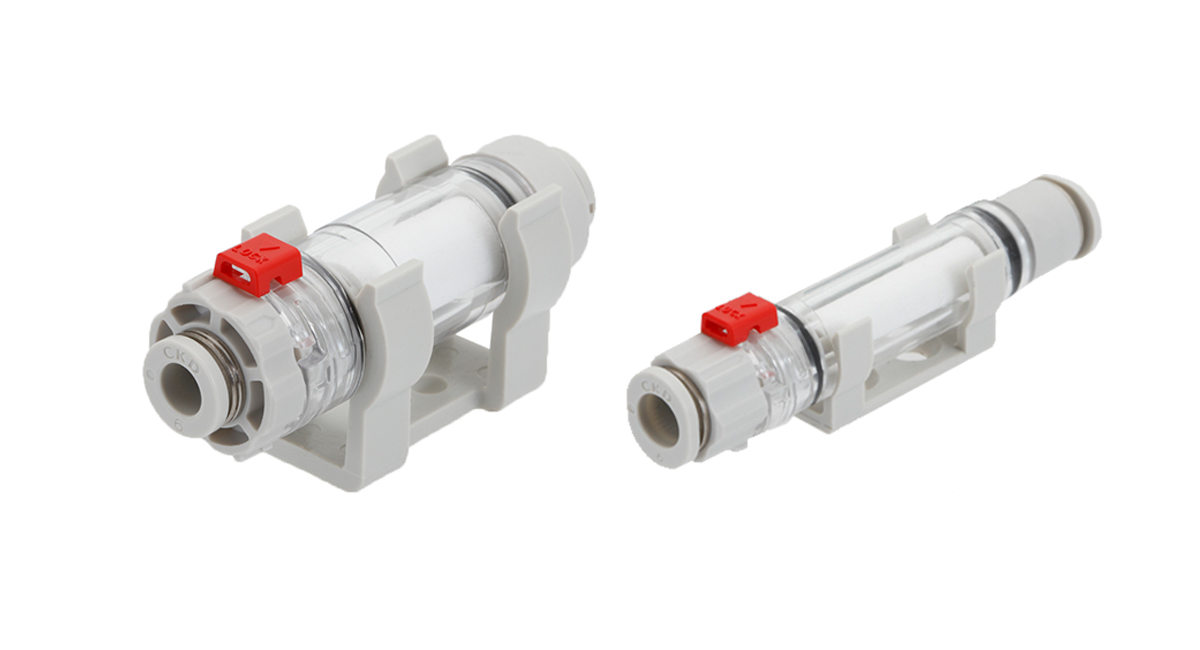
Body (Case):The outer housing that channels the fluid. Materials include PBT resin, polyamide (nylon), and stainless steel, selected according to the operating environment. Products with transparent cases allow visual inspection of internal contamination levels.
Element (Filter media):This is the core component that actually captures foreign particles. It comes in various materials and structures such as non-woven fabric, sintered metal, and hollow fiber membranes, each with different filtration precision and flow characteristics.
Connection port:This part connects to the piping. Options such as Push-in fittings, screw-in types, and flange types are available depending on the installation environment.
Filtration mechanisms (surface filtration / depth filtration)
There are broadly two methods for removing foreign particles using filters.
Surface filtration is a method that captures contaminants on the filter surface. This includes mesh filters and membrane filters, which physically block particles larger than the pore size. While clogging progresses faster with this method, it has the advantage of clearly showing trapped contaminants, making it easier to determine replacement timing.
Depth filtration is a method that captures contaminants within the three-dimensional internal structure of the filter. Non-woven fabrics and sponge-like filter elements fall under this category, trapping particles throughout their thickness. This type allows for a large dust-holding capacity with a small projected area and features a long service life.
Selecting the appropriate method based on the application is key to maximizing filter performance.
Types and characteristics of element materials
The material of the element directly affects cost, durability, and filtration precision.
Non-woven fabric / PVF (Polyvinyl Formal):The most common material, offering excellent cost performance. It also has strong oil resistance and is widely used in general factory air systems.
Sintered metal:Made by sintering metal powder, it can withstand high-pressure and high-temperature environments. Some products are washable and reusable, though initial costs are relatively high.
Hollow fiber membrane:Constructed from bundled straw-like ultra-fine fibers, capable of removing particles as small as 0.01 μm. Its adoption is growing in semiconductor and precision machinery industries.
Types of inline filters [4 types]
There are multiple types of inline filters depending on their purpose and the fluid being filtered. Here we organize four representative types.
| Type | Advantages | Primary applications | CKD products | ||
|---|---|---|---|---|---|
| Disposable type (element replacement type) |
No cleaning required and no risk of secondary contamination | Standard pneumatic piping | FSL FCS SFS |
||
| Cleanable reusable type (metal mesh type) |
Can reduce running costs | Cost-focused workplaces | ‐ | ||
| Positive/Negative pressure dual-purpose type | Bypass circuit unnecessary, enabling simple piping design | Robot hand suction systems | FSL FCS SFS |
||
| Liquid/physicochemical analysis use (HPLC, etc.) |
Compatible with organic solvents and samples with significant pH variations | Protecting analytical instrument columns | ‐ | ||
[Application-specific] Inline filter usage scenarios
Introducing four typical usage scenarios along with challenges/points unique to each application.
| Application | Main risks/challenges | Recommended filtration precision | Product selection points | ||
|---|---|---|---|---|---|
| Protection for pneumatic equipment and air cylinders |
Prevention of foreign object ingress into solenoid valves and cylinders. Seal tape fragments and rust generated in pipelines |
1μm (selected according to application) |
Excessive precision increases pressure loss – select appropriate precision matching spool clearance of solenoid valves | ||
| Vacuum suction lines (robot hands) |
Vacuum level drop/adsorption failure due to foreign object contamination in ejectors or vacuum pad interiors | - | Lightweight and compact design with minimal inertia impact. Dual-purpose type (positive/negative pressure) eliminating bypass circuits | ||
| Semiconductor & precision equipment production lines | Wiring disconnection/short circuits caused by nano-level particles | 0.01μm | Cleanroom specification (clean packaging/low particulate emission design) | ||
| Food & pharmaceutical plants | Foreign object contamination in products. Compliance with HACCP/FSSC22000 etc. |
0.01μm | FDA-compliant materials or stainless steel construction. Chemical resistance for CIP/COP and easy disassembly cleaning | ||
Foolproof inline filter selection [5 key criteria]
Merely browsing catalog spec sheets won't identify the optimal solution for your site. We explain 5 essential criteria for selecting truly effective field products.
1.Compatibility between working fluids and materials
Material selection must match fluids: air, water, chemicals, gases, etc. Special attention required for chemical resistance of resin body components.
PBT resin offers excellent oil resistance, ideal for standard factory air but unsuitable for strong acids/alkalis or high-temperature steam. Polyamide (nylon) provides high oil/alkali resistance while being vulnerable to strong acids. In environments where organic solvents (such as acetone or thinner) are used, there is a risk of resin swelling and cracking, requiring the selection of stainless steel or fluororubber-sealed specifications.
Always verify the chemical resistance chart provided by the manufacturer, and consult the technical support if unsure.
2.Filtration accuracy (how to determine the required μm)
Filtration accuracy does not mean "the finer, the better." Excessive precision leads to increased costs and higher pressure loss.
As a guideline, general pneumatic equipment (solenoid valves, cylinders) requires about 3μm, while semiconductor/precision equipment may need 0.01μm-level filtration.
3.Balance between flow rate and pressure loss
Pressure loss inevitably occurs when passing through a filter. Select the appropriate size based on source pressure and required flow rate, ensuring pressure loss stays within acceptable limits.
Excessive pressure loss can cause slower cylinder actuation, delayed vacuum response, and impact on cycle time.
[Diagram] Relationship between flow rate and pressure loss (Example: CKD FSL series)
The graph below (flow characteristic curve) shows how resistance (pressure loss) increases as the airflow (flow rate) through the filter rises.
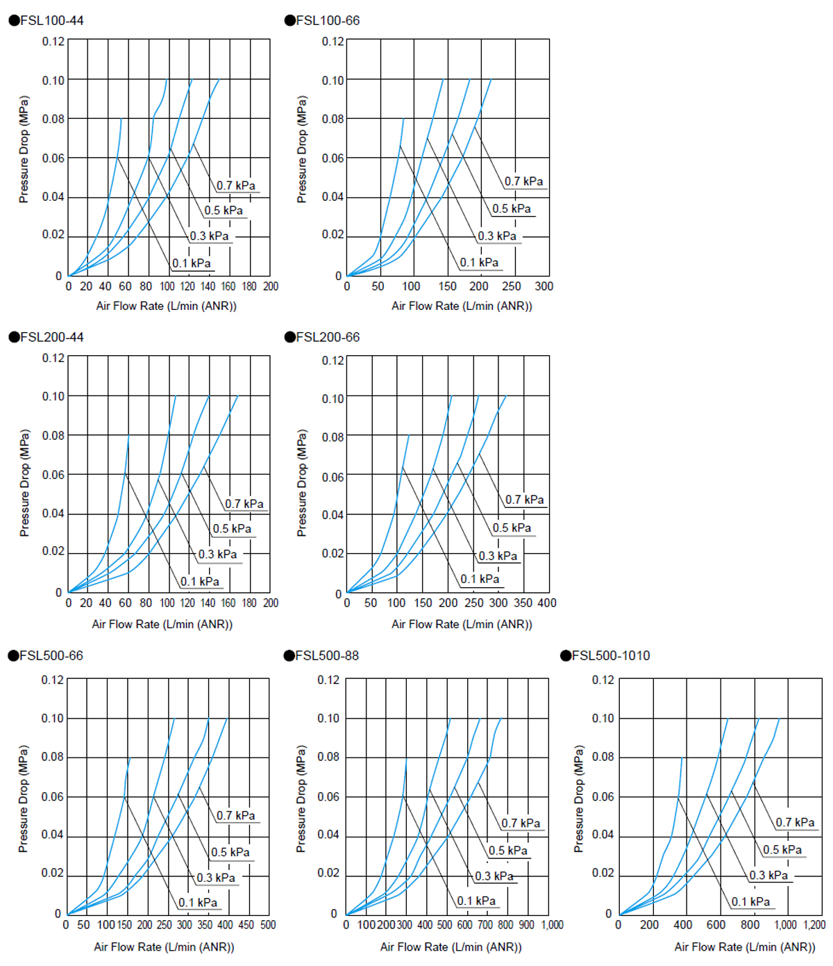
All graphs reveal a sharp spike in the pressure loss curve beyond a certain flow rate (recommended flow capacity).
Manufacturer catalogs specify the "recommended flow capacity." Exceeding this value causes a rapid rise in pressure loss, so selecting a larger size (e.g., one size up) is recommended.
4.Connection method and installation space
For installation in tight equipment interiors or elevated piping, selecting the right connection method and shape is critical.
Push-in fittings simplify piping work, allowing tool-free installation and removal. Elbow or manifold configurations are advantageous in confined spaces. For mounting on robot arm tips, lightweight and compact designs are essential to minimize inertia impact.
Measure the installation space and use 3D CAD data to verify clearance.
5.Maintainability (ease of replacement)
Selection should account for post-installation maintenance. Prioritize products that allow tool-free replacement, especially for high or hard-to-reach locations.
The CKD FSL series adopts a tool-free design. Simply unlock the slide lock and rotate the joint body 180° to replace the element. Since no tools or screws are required, there is no risk of "tools or parts falling into the equipment" during work, providing significant safety benefits.
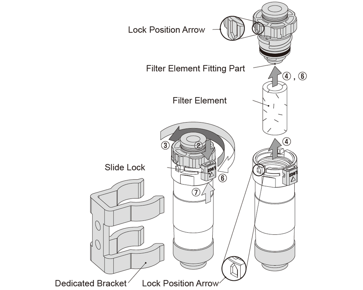
Additionally, transparent casing types allow visual inspection for contamination, making it easier to determine replacement timing and improving preventive maintenance. The reassurance of "visual confirmation" also helps reduce mental stress for maintenance personnel.
Maintenance and replacement procedures
Explains the optimal replacement timing and operational tips to maintain inline filter effectiveness.
How to determine replacement timing
Filter replacement timing varies depending on the usage environment and model, but it is generally determined using the following methods in combination.
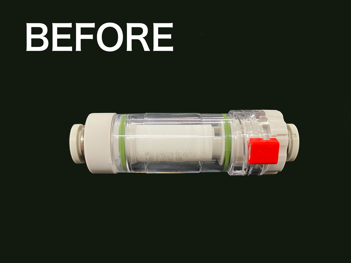
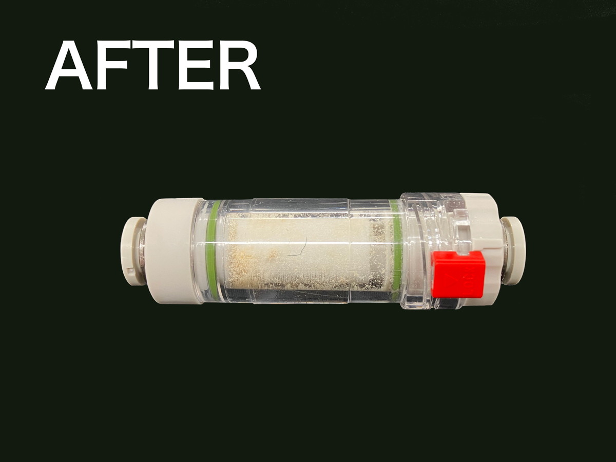
Visual inspection: Check for discoloration (darkening, yellowing) of the element through the transparent casing. Noticeable contamination is one sign that replacement is needed. As shown in the photo below, debris may accumulate. When this happens, it can be a good indication that it is time for replacement.
 |
 |
Differential pressure measurement (recommended): Measure the pressure difference between the primary (inlet) and secondary (outlet) sides. For many models, replacement is recommended when the differential pressure reaches around 0.1 MPa(Varies by product). Using differential pressure gauges or switches enables objective and reliable judgment.
Scheduled replacement: In environments where visual or differential pressure assessment is difficult, a fixed replacement cycle (e.g., "once a year") is commonly used for preventive maintenance. During initial operation, inspect at shorter intervals and adjust the optimal cycle based on observed element contamination.
*Note: Always confirm the exact replacement criteria in the product manual or specifications.
Efficiency tips for replacement work
Tool-free replacement not only reduces work time but also offers major safety advantages.
The CKD FSL series features a tool-free design—simply unlock the slide lock and rotate to complete element replacement.
No tools are needed, enabling quick and safe element replacement while minimizing drop risks in tight or elevated workspaces. Standardizing replacement procedures and maintaining work records are also important. Recording replacement dates, element contamination levels, and differential pressure trends helps optimize replacement cycles and detect early signs of trouble.
Summary
Inline filters are essential components that protect end-use equipments from contaminants generated within pipelines and ensure stable operation of equipment.
They address risks that cannot be fully mitigated by mainline filters installed immediately after compressors, preventing unexpected equipment shutdowns and foreign material contamination in products before they occur.
We strongly encourage utilizing inline filters as a cornerstone of proactive preventive maintenance.
For selecting inline filters, please consult CKD without hesitation.
CKD’s experienced staff will gladly assist with inquiries such as: “I want to install inline filters but don’t know which product to choose” or “I want to introduce products tailored to my company’s challenges.”
We will carefully listen to your challenges and requirements and propose the most suitable products for your needs.