Update history
2024-01-24 Deleted discontinued Model No. and minor revisions made.
・Deleted body sizes up to 12 for ETS, ECS, ETV, and ECV.
2023-08-03 Selected models added.
・EKS-L, FLSH, FLCR, FGRC and FFLD models added.
2023-02-09 Selected models added.
・EBR-G and EBR-L models added.
2022-12-08 Selected models added.
・EBS-G and EBS-L models added.
2018-11-01 The Electric Actuator Selection System has been released.
・It can make single axis selections from ETS, ETV, ECS, ECV, ERL2 and ESD2 Series.
・Please use with Internet Explorer 8 or above.
Before starting the Electric Actuator Selection System,
Cautionary Notes when using the Electric Actuator Selection System
Be sure to thoroughly check the catalog's product specifications and handling precautions before using the selected models.
This Selection System is a simple selection guide, and the calculation results and selected models are not guaranteed by CKD Corporation.
The safety factors are not incorporated into the calculated results, which need to be considered for actual use.
CKD Corporation assumes no responsibility for any damage caused by utilizing this Selection System.
The contents of this Selection System and specifications of the registered products are subject to change without prior notice.
The intellectual property rights such as copyrights on posted data on this Selection System belong solely to CKD Corporation.
The normal operation of the Selection System is when it is used in a normal and standard environment.
CKD is not responsible for the case where the Selection System does not operate in the same manner in the customer's system environment.
Be aware that CKD Corporation will not assume any responsibility for problems and losses caused by the use of the Selection System.
We specifically disclaim all liability for any actions resulting from your use of the Selection System.
You may use and access the Selection System at your own discretion and risk, and you are solely responsible for any damage to your computer system or loss of data that results from the use of and access to the Selection System.
We will not be held responsible for the Selection System to meet your requirements or will be constantly available, uninterrupted, timely, secure, or error-free; the results obtained from the use of the Selection System will be effective, accurate, or reliable; the quality of the Selection System will meet your expectations; or any errors or defects in the Selection System will be corrected.
CKD Corporation, will not be held responsible under any case or circumstances for data loss, loss of profits, restoration costs, other special damages, incidental damages, derivative damages, indirect damages, any damages resulting from business interruption, for gross negligence, for our, or our employees’, intentional misconduct, or for death or personal injury or failure to meet any duty of care, or claims by a third party, even if a CKD representative has been advised of the possibility of such loss, damages, claims, or costs, etc.
CKD will not be held responsible regarding losses and all kinds of damages, regardless of the cause and whose responsibility.
Note: the above details may be changed or deleted without prior notice.
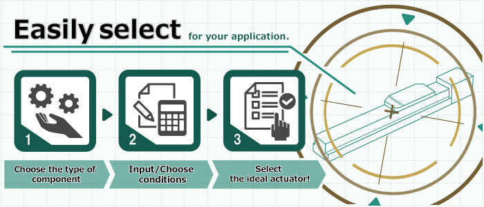
Component selection
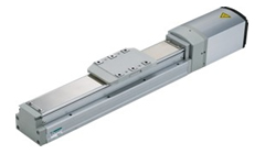
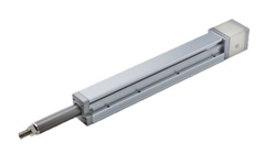
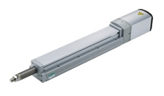
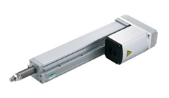
Slider/Rod
EBS/EBR/EKS/ETS/ECS/ETV/ECV
Gripper/Table/Rotary
FLSH/FLCR/FGRC/FFLD
Return
Selection conditions
 | Select typeSelect product type |
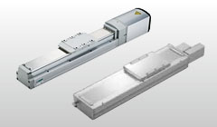
Slider
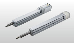
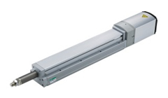
Rod type
| Selection of motor presenceSelect the motor or not |
Motor specification
Specifications for type with motor.
Can be operated with the CKD controller.
Motorless specifications
The product does not come with a motor.
Prepare the motor yourself before use.
Motor specification
Specifications for type with motor.
Can be operated with the CKD controller.
Motorless specifications
The product does not come with a motor.
Prepare the motor yourself before use.
| Select seriesSelect product series |

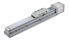
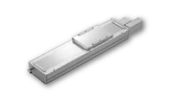
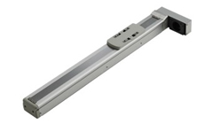
EBS-LE/L※Straight motor mounting/side mounting
Servo motor compatible,Motorless specifications
Ball-screw drive
Stroke length: 50 to 1,250 mm
Max. speed: 1,600mm/s (※)
Max. load capacity: Horizontal 110kg, vertical 33kg
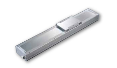
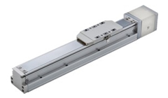
ETSStraight motor mounting/side mounting
Servo motor compatible,Motorless specifications
Ball-screw drive
Stroke: 100 to 1,500mm
Max. speed: 2,000mm/s (*)
Maximum workload: Horizontal 150kg, Vertical: 55kg
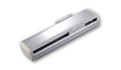
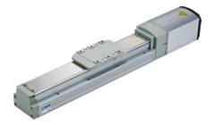
ECSStraight motor mounting/side mounting
Servo motor compatible,Motorless specifications
Ball-screw drive low particle generation type
Stroke: 100 to 1,500mm
Max. speed: 2,000mm/s (*)
Maximum workload: Horizontal 150kg, Vertical: 55kg
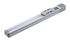
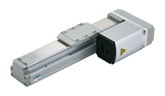
ETVMotor mounting on side/bottom
Servo motor compatible,Motorless specifications
Timing belt drive
Stroke: 100 to 3,500mm
Max. speed: 2,000mm/s (*)
Maximum workload: Horizontal 85kg
ECVMotor mounting on side/bottom
Servo motor compatible,Motorless specifications
Timing belt drive low particle generation type
Stroke: 100 to 3,500mm
Max. speed: 2,000mm/s (*)
Maximum workload: Horizontal 85kg
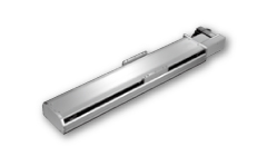
EKS-LEStraight motor mounting
Servo motor compatible,Motorless specifications
Ball-screw drive
Stroke length: 100 to 1,500 mm
Max. speed: 2,500mm/s (※)
Max. load capacity: Horizontal 118.5kg, vertical 33.5kg
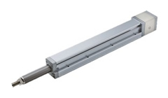
EKS-L※Motor mounting on side/bottom
Servo motor compatible,Motorless specifications
Ball-screw drive
Stroke length: 100 to 1,500 mm
Max. speed: 2,500mm/s (※)
Max. load capacity: Horizontal 118.5kg, vertical 33.5kg
EBS-LE/L※Straight motor mounting/side mounting
Stepper motor compatible,Motorless specifications
Ball-screw drive
Stroke length: 50 to 1,100 mm
Max. speed: 1,000mm/s (※)
Max. load capacity: Horizontal 50kg, vertical 15kg
EBS-GEStraight motor mounting
With stepper motor,For ECG controller
Ball-screw drive
Stroke length: 50 to 1,100 mm
Max. speed: 850mm/s
Max. load capacity: Horizontal 80kg, vertical 43.3kg
EBS-G※Motor mounting on side/bottom
With stepper motor,For ECG controller
Ball-screw drive
Stroke length: 50 to 1,100 mm
Max. speed: 850mm/s
Max. load capacity: Horizontal 80kg, vertical 43.3kg

EBR-LE/L※Straight motor mounting/side mounting
Servo motor compatible,Motorless specifications
Ball-screw drive
Stroke length: 50 to 800 mm
Max. speed: 1,600mm/s (※)
Max. load capacity: Horizontal 110kg, vertical 33kg
EBR-LE/L※Straight motor mounting/side mounting
Stepper motor compatible,Motorless specifications
Ball-screw drive
Stroke length: 50 to 700 mm
Max. speed: 1,000mm/s (※)
Max. load capacity: Horizontal 50kg, vertical 15kg
EBR-GEStraight motor mounting
With stepper motor,For ECG controller
Ball-screw drive
Stroke length: 50 to 700 mm
Max. speed: 900mm/s
Max. load capacity: Horizontal 80kg, vertical 38.3kg
EBR-G※Motor mounting on side/bottom
With stepper motor,For ECG controller
Ball-screw drive
Stroke length: 50 to 700 mm
Max. speed: 800mm/s
Max. load capacity: Horizontal 80kg, vertical 38.3kg
| Select mountingPlease select mounting |
Horizontal mounting
use actuator in horizontal mounting
Horizontal mounting
use actuator in horizontal mounting
Horizontal ceiling (inverse) mounting
use actuator in ceiling mounting

Horizontal ceiling (inverse) mounting
use actuator in ceiling mounting
Wall mounting
use actuator in wall mounting
Wall mounting
use actuator in wall mounting
Perpendicular mounting
use actuator in perpendicular wall mounting
Perpendicular mounting
use actuator in perpendicular wall mounting
Horizontal mounting
use actuator in horizontal mounting
Horizontal mounting
use actuator in horizontal mounting
Wall mounting
use actuator in wall mounting
Wall mounting
use actuator in wall mounting
Perpendicular mounting
use actuator in perpendicular wall mounting
Perpendicular mounting
use actuator in perpendicular wall mounting
| Selection of drive method and multi-axial combination.
Please select multi-axial combination. |
2-axes X-Y combination
ball-screw drive
2-axes X-Y combination
timing belt drive
2-axes X-Z combination
ball-screw drive
2-axes X-Z combination
timing belt drive
2-axes Y-Z combination
ball-screw drive
2-axes Y-Z combination
timing belt drive
2-axes Z-Y combination
ball-screw drive
2-axes Z-Y combination
timing belt drive
3-axes X-Y-Z combination
ball-screw drive+ball-screw drive+ball-screw drive
3-axes X-Y-Z combination
timing belt drive+timing belt drive+ball-screw drive
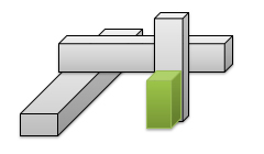
4-axes X-Y-Z-R combination
ball-screw drive+ball-screw drive+ball-screw drive+Raxis
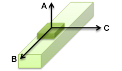
Enter load conditions
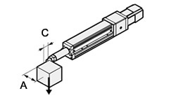
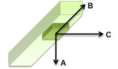
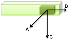
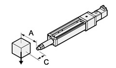
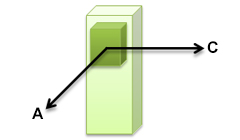
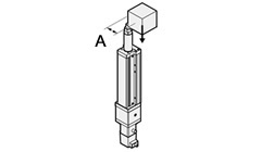
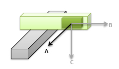
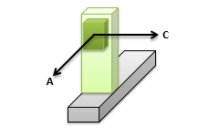
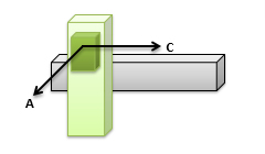
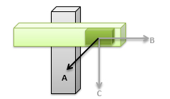
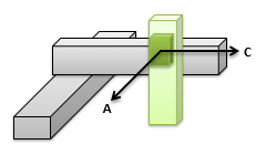
Please enter the distance between the workload and center of gravity. |
After specifying the No. of workpiece combinations, enter the payload of the workpiece and the distance from the jig to the center of gravity for each combination.
- No. of workpiece combinations
| Work No. | Workload (kg) | A (mm) | B (mm) | C (mm) |
|---|---|---|---|---|
| Work 1 | ||||
| Work 2 | ||||
| Work 3 | ||||
| Work 4 | ||||
| Work 5 | ||||
| Work 6 | ||||
| Work 7 | ||||
| Work 8 | ||||
| Work 9 | ||||
| Work 10 |
Horizontal mounting
 | Enter movement conditions
Please enter travel conditions |
Select the input method and then enter the operating conditions.
Travel conditions
- Model
- Lead
- Maximum workload
- M=kg

- Stroke
- S=mm
- Acceleration time
- Ta=s
- Deceleration time
- Td=s
- Acceleration
- a=m/s2
- Deceleration
- d=m/s2
- Acceleration
- a=G
- Deceleration
- d=G
- Speed
- V=mm/s
- Movement time
- T=s
- Operating direction
- Motor brake
- Stop stabilization time
- Td=s
- Pause time
- Pt=s
Timing chart
- Distrance travelled
- S=mm
- Travel time
- T=s
- Effective speed
- Vb=mm/s
A suitable model cannot be found for the conditions entered.
Please try changing the entered value(s).
Some values entered are beyond the range.
Lead matrix table
| Motor size (W) |
| Model |
| Lead (mm) |
| Maximum speed (mm/s) |
| Stroke (mm) |
| Motor size (W) |
| Model |
| Lead (mm) |
| Maximum speed (mm/s) |
| Min. speed (mm/s) |
| Stroke (mm) |
Enter travel conditions
Please enter travel conditions |
After selecting the input method, please enter the travel conditions
Travel conditions
- Maximum workload
- M=kg
| Movement distance(mm) | | |||
| Movement time(s) | |
A suitable model cannot be found for the conditions entered.
Please try changing the entered value(s).
Some values entered are beyond the range.
The script required for selection could not be executed or data retrieval failed.
This system cannot be operated on your local drive. Please utilize it from the WEB server.
Please confirm if you are connected to the Network.
If Network conditions are met but problems persist, please try again at a later time or try changing your browser.
Selection results

Selection conditions
| Type | |
| Series | |
| Travel conditions | Enter method Model and lead Input value Input method Input value |
Mounting type
Multi-axial combination
Workload conditions
| No. of combinations | ||||||||||||||||||||||||||||||||||||||||||||||||||||||||
| Workload | ||||||||||||||||||||||||||||||||||||||||||||||||||||||||
| Amount of overhang | ||||||||||||||||||||||||||||||||||||||||||||||||||||||||
| ||||||||||||||||||||||||||||||||||||||||||||||||||||||||
Calculation results
*Display the result of the axis with the long travel time
| Specified value | Calculated value | |||||||
| Distrance travelled | mm | ≧ | mm | ... | ||||
| Workload※ | kg | ≧ | kg | ... | ||||
| Speed | mm/s | ≧ | mm/s | ... | ||||
| Acceleration | mm/s2 | ≧ | mm/s2 | ... | ||||
| Deceleration | mm/s2 | ≧ | mm/s2 | ... | ||||
| Acceleration | G | ≧ | G | ... | ||||
| Deceleration | G | ≧ | G | ... | ||||
| Acceleration time | s | ≦ | s | ... | ||||
| Deceleration time | s | ≦ | s | ... | ||||
| moment | N・m | ≧ | N・m | ... | ||||
| Ball screw expected service life | km | ≦ | km | ... | ||||
| Guide expected service life | km | ≦ | km | ... | ||||
| Allowable load weight | kg | ≧ | kg | ... | ||||
| Regenerative power | W | ≧ | W | ... | ||||
| ※ Load weight is the max. allowable load weight of actuator. As the motor performance is not taken into account, contact the motor manufacturer. | ||||||||
Operation results
| Distrance travelled | S= | mm | ||
| Acceleration distance | Sa= | mm | ||
| Deceleration distance | Sd= | mm | ||
| Constant speed distance | Sc= | mm | ||
| Travel time | T= | s | ||
| Acceleration time | Ta= | s | ||
| Deceleration time | Td= | s | ||
| Constant speed time | Tc= | s | ||
| Effective speed | Vb= | mm/s | ||
| Acceleration | a= | mm/s2 | ||
| Deceleration | d= | mm/s2 | ||
| Acceleration | a= | G | ||
| Deceleration | d= | G | ||
| Speeds reached | Vmax= | mm/s | ||
| Ball screw expected service life | Lb= | km | ||
| Guide expected service life | Lg= | km | ||
| Allowable load weight | Lm= | kg | ||
| Regenerative power | Rp= | W |
Timing chart